feasible.
Im working now since 2008 on my "project".
Eliminating step by step the drawbacks of stability.
And learning a lot of real and not ideal parts.
plastic DIP devices being about a factor 3 better than SMD.
hysteresis.
year.
eliminates humidity if carefully decoupled from PCB stress.
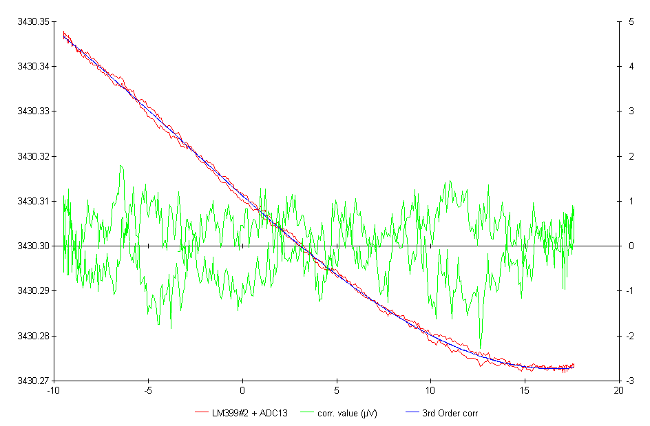
compensation is shown in the attached picture. (ADC13_TC)
reference via a 2:1 capacitive divider.
measured directly at the AD586 reference.
Y-Axis on the left is LM399 measurement value in mV (divided by 2).
The red line is the measurement value of the ADC. The blue line the
resulting correction with a 3rd order polynominal.
deviation in uV after calculating out the tempco of the reference.
resulting tempco after correction.
1.1ppm). Together with my temperature resolution of about
0.6uV/step in the 5V-Range of the ADC.
measurements.
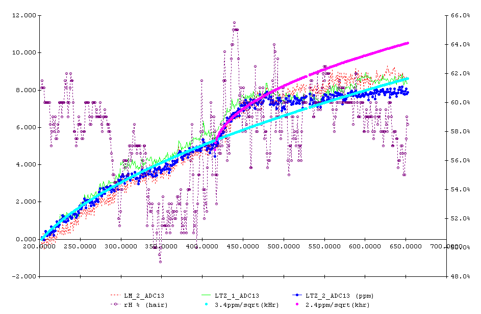
After a run in phase of nearly 1 year the ageing of ADC #13 stabilized.
= LM_2 and 2 LTZ1000A = LTZ_1/2).
to the heated references.
ADC13 reference.
thermocouples.
Ok my temperature step noise is still too high. And probably I am using the
2 relative close neighboured contacts.
Post by Andreas JahnAndreas
1st my two cents worth concerning comments of others that are being more
practical than nutty.
"it is not easy to achieve these specs",
Too True,
If you do not already know this, then I'd suggest you back off and do some
major readjustment of your requirements.
Assuming you already know it is not easy and why, then
IMHO, what you want to make is doable with the right compromises, some of
which being
A little extra power.
a lot of extra time
a lot of test selecting
some extra circuits or S/W
"your expectations are not realistic "
True, if you think it can be done from a data sheet and a few of off the
shelf parts in a production device.
Not true, if you want to go totally nuts and have the time to do it.
"The thermoelectric effects causing error would swamp the performance"
Could be true for some. If you do not already know enough to keep these
effects well under <<0.1PPM then should find another starter project.
"To keep everything below the 1 ppm/deg C range you would have to put the
entire circuit in controlled temperature"
Too true, But for these requirements, fortunately you do not have to keep
*Everything* under 1 ppm/deg C
ALL you have to do is to keep the sum total of Everything under 1ppm. Big
difference!
And that is very easy to do, by a fact of ten plus if desired.
"long term drift and noise will be intrinsic to the devices, and
unpredictable except in a statistical sense."
Half true,
Using the *right device*, and a lot of time, noise can be low enough to be
mostly insignificant
and long term drift will follow a predicable slope.
It ain't easy and it's going to take a lot of time. If you think
otherwise, you need a new project..
"provide near zero tempco at one temperature only"
Answer too limited to be useful
zero TCing a circuit, can provide no voltage difference at any two
temperatures, (to the limit of the repeatability)
Depending how flat you need it between these two temperatures, is the only
issue.
Best to plan on having a second order TC method as well.
A total max total deviation of 1ppm and a 0.1 PPM /deg is not too hard to
get.
"One of the best voltage standard Datron 4910AV (4x LTZ1000) have only 1
ppm/year drift"
OK, so that shows there is at least one way to do it, so it is not
impossible.
Now just need to find the best way for you to do it.
"Don't bother with TC zeners"
Not a bad idea, but Unfortunately Not a lot of other choices considering
your requirements.
The other choice you have (that you should consider if time is a big issue)
is to get some three terminal Fluke voltage references.
If necessary by removing them from old test equipment such as Fluke 731
Those have already been selected and aged, and you'd just then need to
work on the long term drift compensation selection method.
"There are lots of nice IC references available"
True, and if you can live with data sheet specs, they are much better
choices.
But hard if not impossible to find anything that will compare to 1/F pop
corn noise, and long term stability
"I doubt that any TCZ will match an LM399"
True when considering a wider temperature range, and it sure makes things
easier,
so a good suggestion if TC was your main problem.
But TC need not be a problem, and most any good zener will outperform most
any selected LM399 in low freq noise and stability.
"so would have to be ovenized to get *best* performance".
True of Any circuit when "best" TC is concerned, so not very relevant,
The question is can it be made good enough without an oven?
And the answer is defiantly yes with the right tempco circuit.
And if you want it even better, can make a very low power mini-oven.
Back to your email ******************
Post by Andreas JahnDo you have typical values over a 64-90 ?F range. Will it be above 1ppm/K
or below?
I do not have any data over that Temp range in front of me.
Over My room changes (about 1/2 that temp range), can keep the Total
voltage error down to around 1PPM, (not just /deg)
If it is an important consideration, I may try and see what happens over a
wider range.
For a backup plan, considering having an addition second order TC
compensating method such as S/W.
Overall compensating to 1ppm / C is no problem,
which is Total change +- 7PPM over a +- 7 deg C range
Ten times better is possible over narrow temp ranges like that.
It is the hysteresis and stability that is going to be a limiting factor,
and last I looked,
The zeners I tested had no measurable Hysteresis over a much wider temp
range than that.
Post by Andreas JahnPost by WarrenSFrom your plot it would be 0.33ppm per 3 degrees in narrow range i.e. 0.1
ppm per degree.
Correct, but not a relevant measurement.
ANY straight line TC as seen there can be zeroed out.
That was just a pre-test plot to see if the part was low enough noise to
do a more accurate Zero TC.
Post by Andreas JahnBy the way: is it degrees Fahrenheit or degrees Celsius (= 3 Kelvin)?
My world is mostly in F, and since I was not even plotting temp at the
same time, pretty irrelevant for that data set.
Post by Andreas JahnIf I understand you right then you would not use this device because it
does
behave other than the others?
Your understaning is not correct, not even close. My comment applies to a
preselection process of 1N82x parts.
In the case you stated, your preselection process (assuming you have
enough to pick from) would be to select all the parts that are less than
say 1PPM, with maybe a 20% yield.
If the yield is too low then make a second pass for parts that are say 2
+-1 PPM,
and in that case, then yes the "best" part would not go into that batch,
because it will likely need a different compensation than the others.
Post by Andreas JahnOn the other side it seems to be the device with the largest ageing rate
of the 5 pieces.
likely too little data to be important, Just as likely random luck as
anything important.
Until after you do some pre-aging, (whatever that may mean for that part)
I would not even bother looking at that data this early on in the
selection process.
Post by Andreas JahnSo I still hope that anyone has experiences with hysteresis of the zeners.
Turn on after power down, and hysteresis, repeatable, etc altogether is
under 1PPM.
As part of my pre-test TC procedure, I hit them with cold spray to 0 C and
heat them with a heat gun to ~50C, a few times,
If they are not repeatable they are not used in further testing.
I have a question about two of your requirements
AJ> tempco below 1ppm/K
AJ> hysteresis in the 10-40 degree range well below 1ppm
This suggest to me that what you are really planning on making is
something with an overall compensted TC that is well below a 1 ppm/K,
otherwise your hysteresis requirement does not make a lot of sense to me.
So if what you are really after is more like < 1 PPM total error over time
and temp, all this extra trouble now makes a lot more sense.
Now the disclaimer, I have no idea if any of the now available 1N825 or
better parts work like I've described.
It is VERY much a manufacture sensitive thing.
Short term noise being the biggest rejecting thing I've seen in the past.
0.5 PPM (3uv steps) are not untypical for some batches.
If someone that has enough of these parts from a single batch and
manufacture to make it worth while testing them, and will make them
available to others, then I'll test and report the results and compare
them to what I have.
There may be another less direct way to get where you want to go (You did
not say where that was)
Divide the task into two or more sections.
As an example, One being the low power short term stable DVM device that
works over a limited temperature.
There would be no problem getting 0.1 PPM accuracy/repeatable for that part.
and a second higher power device that is mostly off, and powered up Just
long enough to calibrate the low power xfer DVM above.
And if you can then include some sort of cal exchange program for the
higher powered but less used device, this would make a very hard project
into a relative easy project.
ws
_______________________________________________
volt-nuts mailing list -- volt-nuts at febo.com
To unsubscribe, go to
https://www.febo.com/cgi-bin/mailman/listinfo/volt-nuts
and follow the instructions there.
A non-text attachment was scrubbed...
A non-text attachment was scrubbed...
 >
> >
>